Electric Lunatic
www.ElectricLunatic.net
TTL SVGA
Vertical Signals
Synch and Blanking
Vertical Signals Generator Circuit Schematic
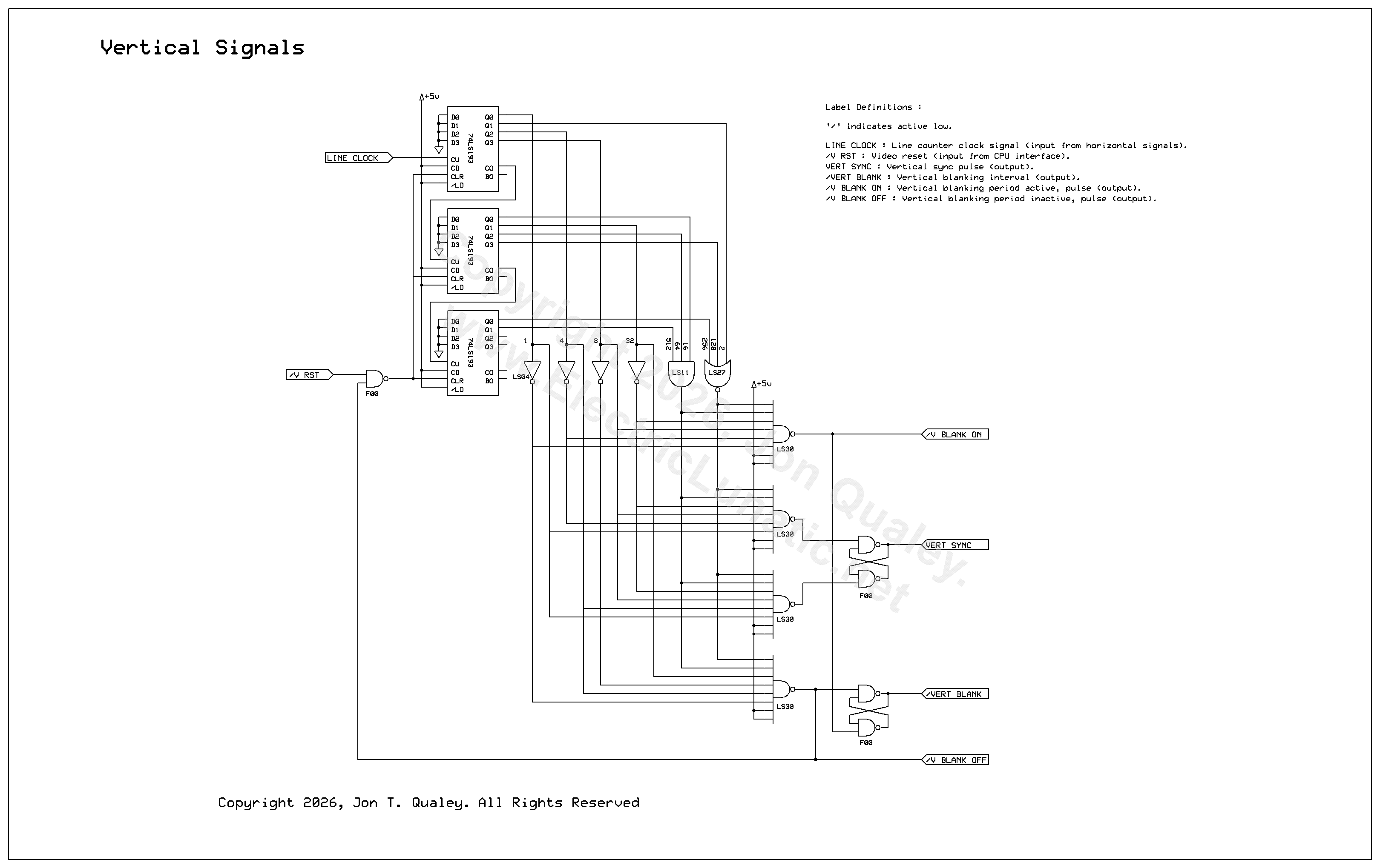
As stated in the introduction, this circuit was inspired by an SVGA project by Ben Eater. The vertical signals generator is not a verbatim copy of Ben's cricuit but is very similar. A link to Ben Eater's SVGA board project is here : https://www.eater.net/vga
Vertical Signals Timing
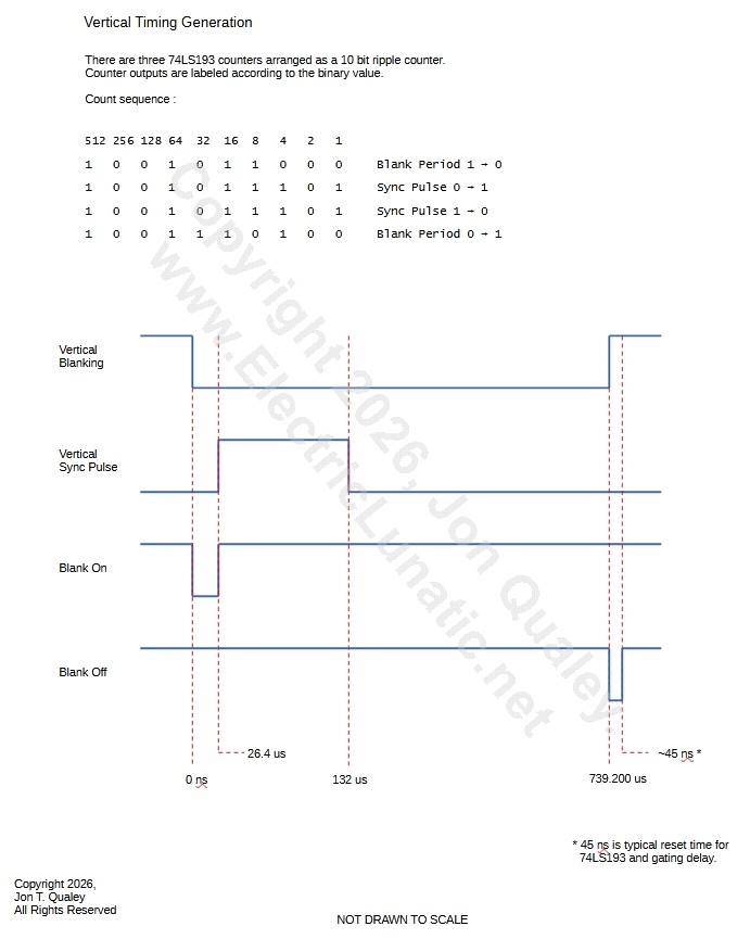
The diagram shown above illustrates the timing of the vertical synchronization and blanking signals in relation to the vertical signals generator circuit.
Circuit Description
Like horizontal timing, vertical timing is generated by three 74LS193 binary counters connected in tandem. The first counter is clocked by the LINE CLOCK signal from the horizontal signal generator. This is the pulse that indicates the end of the horizontal blanking period.
A 3 input NOR gate, 3 input AND gate, along with inverters and 8 input NAND gates are connected to make four identity detectors that generate the start and stop pulses of the vertical synch pulse and vertical blanking period. The 3 input NOR gate consolidates one output from each of the counters as they are always 0 for all four generated pulses. Likewise, the 3 input AND gate consolidates three outputs from the counters as they are always 1 for all four generated pulses.
Like the horizontal timing circuit, four NAND gates are used to make two RS latches, which generate the vertical synch and vertical blanking period signals. In this circuit, the 74LS00 can be used for the RS latches, but I chose to use the 74F00 to tighten up the timing a bit.
The pulses indicating the start and stop of the vertical blanking period are used to notify the host CPU that the vertical blanking period is active so that the CPU may write to video memory. These are labeled /V BLANK ON and /V BLANK OFF
Copyright 2026, Jon T. Qualey. All Rights Reserved
Back To TTL SVGA