Electric Lunatic
www.ElectricLunatic.net
TTL SVGA
Host CPU Interface
Host CPU Interface Circuit Schematic
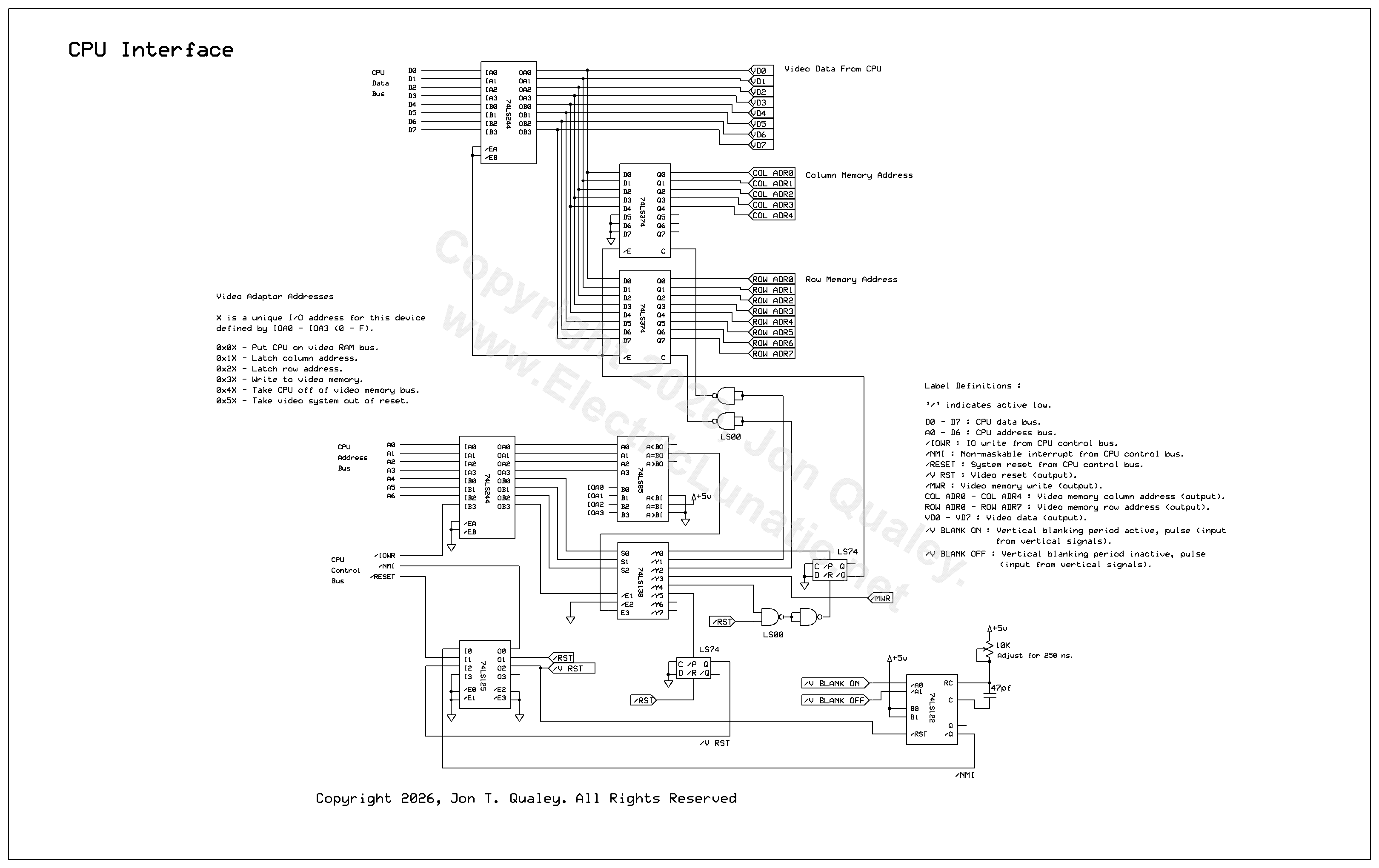
Circuit Description
The CPU interface is fairly straight forward. When the host CPU is to write to video memory, the row and column addresses are written through the CPU data bus and latched. The byte to be written to video memory is then sent through the CPU data bus and written to video memory.
The lower 7 bytes of the address bus are used to address the video adapter. The 4 least significant bits in the address (A0 - A3) contain the unique IO address of the video adapter. Bits A4 - A6 contain the operation code that determine the action being taken by the host CPU. The unique address of the video adapter are set in the video card and can be from 0 through 15.
The host CPU is notified when the vertical blanking period starts and ends through an interrupt. In this implementation, a non-maskable interrupt is used. The host CPU can write to video memory only during the vertical blanking period. The duration of the vertical blanking period is 739.2 us.
The video adapter powers up in a reset state and has to be taken out of reset by the host CPU. This is to ensure that the video adapter does not send any interrupts when the vertical blanking state change before the host CPU is ready to process these interrupts.
CPU Control Bus
The IO write and reset signals from the host CPU are buffered with a 74LS244 and a 74LS125. The interrupt signal sent to the CPU is also buffered with a 74LS125. (A '244 or '541 (either LS or HCT) could be used instead of a 74LS125 as they have the advantage of having Schmitt trigger inputs. I used the 74LS125 because of the physical board arrangement. After the board was built I realized I could have used a 74LS14 for the control signal inputs.)
CPU Address Bus
The CPU address bus is buffered with a 74LS244. The least significant 4 bits of the address are sent to a 74LS85 four bit magnitude comparator. This identifies the video adapter IO address. Operation codes are not executed unless the address matches. The video adapter IO address is set at the second 4 bit input on the 74LS85. This can be hard wired or set with DIP switches, or any other method suitable for the application.
Bits A4, A5 and A6 of the CPU address bus contain the operation code. The operation code is decoded by a 74LS138. The outputs on the 74LS138 are enabled by the equality output from the 74LS85 and the IO write signal from the CPU.
CPU Data Bus
The CPU data bus is buffered with a 74LS244 buffer. The output of the buffer is connected to the data bus of the video memory and to two 74LS374 latches that store the row and column address.
The 74LS374 was chosen because the outputs are tri-state and can be put into high-Z state when video memory is not accessed by the host CPU. The 74LS244 and two 74LS374 latches are taken in and out of high-Z at the same time. This means that the data, row and column address have to be enabled on video memory address and data bus (with op-code 0x0X) prior to latching the row and column address. Otherwise, the row and column latches will not receive data from the data bus.
All data written to video memory must be completed during the video blanking period and the data, row and column address from the CPU must be disabled before the vertical blanking period ends. The row and column addresses generated by the video adapter when reading video memory are buffered using tri-state buffers (74LS244) and are put into high-Z state during the vertical blanking period to allow the host CPU access to video memory.
Reset
The video adapter is held in reset at power up until the host CPU takes the video adapter out of reset. This is done to prevent the video adapter from sending interrupts when the vertical blanking state changes before the host CPU is ready to process the interrupts. This is done with a 74LS74 RS flip-flop that is reset upon power up and set when the host CPU sends the 0x5X operation code.
Vertical Blanking Period Notification
An interrupt is sent to the host CPU when the vertical blanking period starts and ends. It is the responsibility of the host CPU to keep track of when the vertical blanking period is active (more about this later in the software section).
A 74LS122 one shot is used to ensure that the interrupt signal sent to the CPU is long enough in duration. In this implementation of the video adapter, the interrupt pulse width is set to approximately 250 ns.
Board Address And Operation Codes
The operation codes sent to the video adapter in bits A4, A5 and A6 of the address bus are as follows :
- 0x0X - Enable the row and column address, and data on the video memory address and data bus.
- 0x1X - Latch column address.
- 0x2X - Latch row address.
- 0x3X - Write data to video memory.
- 0x4X - Disable the row and column address, and data on the video memory address and data bus.
- 0x5X - Take video adapter out of reset.
Where X is video adapter IO address and may be 0 - F.
Host CPU Software
In the author’s implementation, the host CPU is a Z80A, so the software examples shown are written using the Z80 instruction set.
The non-maskable interrupt on the Z80 is used by the video adapter in my implementaion. The maskable interrupt is used for the keyboard interface. Not all CPUs have more than one interrupt (if any) so an interrupt priority encoder (74LS147, '148 or '748) might be used. (On the other hand, the 8085 has a rich interrupt structure, as do many controllers.)
The host CPU has to keep track of when the vertical blanking period is active. The non-maskable interrupt is used to notify the CPU when the vertical blanking period starts and ends. To implement this, the non-maskable interrupt handler toggles the video blanking state in memory. Before the CPU writes to video memory, it must check the video blanking state to ensure that it can access video memory and also that the blanking state has just started.
Interrupt Handler
The interrupt handler loads the vertical blanking state value from memory and simply compliments the value. It doesn’t specifically set the vertical blanking state to any particular value. This is why it is important for the video adapter to be held in reset until the host CPU sets the vertical blanking state to “off”. (The value shown for V_BLANK_STATE is what I used in my implemnentation, but any memory location can be used.) Here’s a code snippet :
                    V_BLANK_ON:     EQU 0xF0   ; Indicates that video blanking state is active.
                    V_BLANK_OFF:    EQU 0x0F   ; Indicates that video blanking state is inactive.
                    V_BLANK_STATE:  EQU 0x2267 ; Video blanking period state location.

                    ;
                    ; NMI service routine at 0x0066. This is used by the video interface to toggle the video
                    ; blanking period flag. It is safe to write to video memory during a blanking period.
                    ; This routine requires 52 clock cycles. At 4MHz, that's 13 us.
                    ;
                    EX AF, AF'                 ; Preserve A and F.
                    LD A, (V_BLANK_STATE)      ; Load blanking state flag into A.
                    CPL                        ; Compliment the blanking state flag - toggle between blanking
                                               ; period on and off.
                    LD (V_BLANK_STATE), A      ; Write the blanking state flag back to memory.
                    EX AF, AF'                 ; Restore A and F.
                    RETN                       ; Return.
In this case, the Z80 CPU has a compliment set of registers. For other CPUs that do not, the accumulator (and other necessary registers) would be pushed and popped to and from the stack.
The reader may be wondering why the vertical blanking state is stored in a memory location at all. Why not just store it in A' and simply use EX AF, AF' to swap the vertical blanking state flag in and out of A?
There is a good reason for this. If the vertical blanking state were stored in A', the video write routines would also have to execute EX AF, AF’ to check the vertical blanking state. If vertical blanking state changes while the video write routines have A and A' swapped, the value in A would be complimented instead of A', changing the value in A and not changing the vertical blanking state in A'. Remember that the vertical blanking state is change via a non-maskable interrupt. The video routine checking the vertical blanking state doesn’t “know” that the non-maskable interrupt handler has swapped A and A' while it is executing.
Checking The Vertical Blanking State
The host CPU has to check the vertical blanking state before writing to video memory. If the blanking state is active, its safe to write to video memory. But there is a problem to deal with...
If the video writing routine checks the vertical blank state and finds that it is active, there is no way to determine how long the blanking state has been active and how much longer the blanking state will remain active. So if the blanking state is active when the blanking state is checked, the CPU must wait until the blanking state becomes inactive, then active again. This way the time available to write to video memory is known. Otherwise, if the blanking state is inactive when checked, the CPU would simply wait until the blanking state becomes active.
Here is a code snippet for checking the blanking state in my implementatio :
                    V_WAIT_NBP:     LD A, (V_BLANK_STATE)    ; Get video blanking state.
                                    AND V_BLANK_ON           ; AND it with ON to check.
                                    JP Z WAIT_VBS_ON         ; Blank off, wait for on.

                    WAIT_VBS_OFF:   LD A, (V_BLANK_STATE)    ; Blank on, wait for off.
                                    AND V_BLANK_OFF          ; AND it with OFF to check.
                                    JP Z WAIT_VBS_OFF        ; Blank on, wait for off.

                    WAIT_VBS_ON:    LD A, (V_BLANK_STATE)    ; Get video blanking state.
                                    AND V_BLANK_ON           ; AND it with ON to check.
                                    RET NZ                   ; Return if blank on.
                                    JP WAIT_VBS_ON           ; Check again.
When used in conjunction with above shown routine to toggle the vertical blanking state, upon return of this routine, 87 machine cycles (on a 4MHz Z80A) have elapsed since the vertical blanking state has changed. Running on a Z80A at 4 MHz, that’s 21.75 us. This leaves 717.45 us for the host CPU to write to video memory.
Writing To Video Memory
Going into great detail about how to write to video memory is beyond the scope of this document, as it mostly depentent on the host CPU system. However, in brief, writing a single byte to video memory would be done like this :
- Send 0x0X using an OUT instruction (or equivalent) to put the CPU interface on the video memory bus. The actual data sent is irrelevant for this operation code – sending a zero will do.
- Send 0x1X with the column address as data. This is latched into the 74LS374 designated for column address.
- Send 0x2X with the row address as data. This is latched into the 74LS374 designated for row address.
- Send 0x3X with the byte to be written to video memory as data. This writes the data into video memory at the column and row address.
- Send 0x4X to take the CPU interface off of the video memory bus. Like op-code 0x0, the data sent is irrelevant.
Where X is the IO address of the video adapter and may be 0 - F.
Also, remember that the video adapter is set into reset upon power up. After the CPU has performed all necessary initialization and is ready to process vertical blanking period change interrupts, send 0x5X to take the video adapter out of reset.
Writing Multiple Bytes
More than one byte can be written per blanking period, but the number of bytes written depends on the CPU type and clock speed and such. Machine cycles for a specific CPU and clock speed would have to be counted. The CPU interface would be taken on and off the video memory bus once. Row column addressed would be sent one or more times along with data while the CPU interface is enabled on the video memory bus.
Writing Text Characters To Video Memory
To render text on the video screen, character bit maps would be stored on the host CPU. The author implemented video text by storing 8 bit maps per character to render an 8x8 character on screen. Since a byte written to video memory will be displayed horizontally, 8 bit maps are sent for the same column, each one on the next row.
Remember that the video memory in this video adapter cannot be read. So it is the responsibilty of host CPU to keep track of where the editing cursor is located (if any) and what has been written to video memory.
I can furinish the bit maps I used for characters in my system upon request. However, my character are upper case only and could be implemented better.
Copyright 2026, Jon T. Qualey. All Rights Reserved
Back To TTL SVGA